The first stage of the design phase was analysing the requirements and understanding how they would have affected the rocket subsystems. The team had to come up with a preliminary design at the end of the first three weeks and present it to the senior members of the society. In this way the design could be reviewed and a check of the progress of the subsystems could be carried out.
The first step was sketching and coming up with ideas for the rocket systems; as a matter of fact the WBPP started dividing the rocket in three sections:
A starting point for the conceptual design of the rocket was Open Rocket. The programme allowed the team to understand how the various design choices quantitatively affected the rocket and its performances; the maximum height, the static stability, the flight time and the exit velocity of the rocket could be estimated.
An initial brain-storm led the team to establish that the one of the following solution could be implemented on the rocket for each subsystem. The level of detail of this design phase is still less than 50% accurate with respect to the final design.
The first step was sketching and coming up with ideas for the rocket systems; as a matter of fact the WBPP started dividing the rocket in three sections:
- Upper section: this section would have contained the payload, and the electronics
- Middle section: this section was dedicated to the parachute; from the beginning the team opted for an axial recovery system that would split the rocket in two parts.
- Lower section: the engine which was already provided and it was not object of the design nor investigation.
Exploration
An exploration design process started; considerations and design solution were evaluated and a list of problem to address was outlined:- How is the 200N thrust load going to be distributed over the structure
- How is the parachute going to be deployed
- What structure will contain the payload and the electronics
- Which materials would the rocket be made out of
- What manufacturing techniques and skills would be needed to build the rocket
- Which secondary mission should be included
A starting point for the conceptual design of the rocket was Open Rocket. The programme allowed the team to understand how the various design choices quantitatively affected the rocket and its performances; the maximum height, the static stability, the flight time and the exit velocity of the rocket could be estimated.
An initial brain-storm led the team to establish that the one of the following solution could be implemented on the rocket for each subsystem. The level of detail of this design phase is still less than 50% accurate with respect to the final design.
- In order to have a stiff and lightweight rocket able to withstand a 200 N load, the team chose to work either with a carbon fibre or with glass fibre. These materials will be used to build the outside shell tube of the rocket. Both of the options, however, presented manufacturing challenges: firstly we had to come up with a method of laying up the fibres obtaining a tube like shape; secondly we had to find a way to minimize the air bubbles inside the tube.
- As mentioned above, the parachute would have opened up the rocket in two parts: the engine and the upper section containing the payload. In this manner, by attaching a longer parachute rope to the engine and a shorter one to the payload the landing of the upper section would have been much softer increasing the chance for the egg to survive. The mechanisms to open the parachute considered for the mission are the following: a pyro charge that detonating would separate the parachute in two parts and shoot out the parachute; a servo used to pull up a set of longitudinal pins keeping the rocket and middle and the lower part together; eventually it was also considered the option of separating the rocket in two parts using the air pressure created by a tyre inflator for instance.
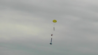
Illustration of the engine section landing first and the payload after with a lower speed - The internal skeleton of the rocket was subject of strong debate between us; everyone knew that it was extremely important in order to transfer the thrust loads and the shock load at when the parachute opened from the point loads to the skin. At the same time, the structure had to provide attachment for the electronics and the payload. Two solutions were considered: a combination of 3D printed payload bay for the egg and for the electronics or a "stage" like structure made of different bulkheads to sustain the payload and the electronics.
- Different materials were considered for different components according to their functions; the structural bulkheads in the rocket were initially thought to be either in steel or in aluminium since they could be easily lathed or laser cut in case of aluminium. In addition balsa wood was also thought to be a good choice for the nose cone because of its lightweight property.
- The team soon realised that in order to work with any composite it was crucial to find a way to produce tube like shape laying up fibres with resin. The solution adopted is described in the post "Manufacturing Techniques". In addition it was also needed to be able to work with a lathe, design on a programme such as CATIA or SolidWorks in order to produce a drawing to laser cut or 3D print any piece.
- Because the team was so focused on reaching the objective of bringing back the raw egg without breaking it, the only secondary mission that was considered was measuring the maximum altitude that the rocket would have reached thanks to a pressure sensor that would have also used to deploy the parachute

Commenti
Posta un commento